Wiring NMEA 2000 Networks for Modern Boating Gadgets: Setup Guide
Learn how to wire and integrate a NMEA 2000 backbone for your boating gadgets. Step-by-step setup guide for sonars, GPS, and battery monitors.
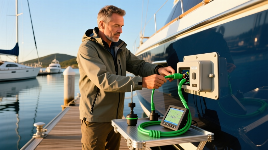
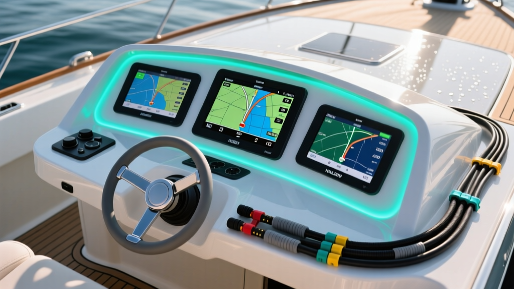
Setting up modern marine electronics is no longer just about mounting a screen and running a power cable. As we navigate the 2026 boating season, the integration of high-definition sonar, automated trolling motors, and lithium battery management systems requires a flawless data network. If you are upgrading your vessel, understanding how to wire and integrate a NMEA 2000 backbone for your essential boating gadgets is the most critical DIY skill you can develop. This tutorial will walk you through the exact topology, wiring standards, and integration steps required to build a robust, error-free marine network.
The Backbone of Modern Marine Electronics
The NMEA 2000 (National Marine Electronics Association 2000) standard is the universal language for marine electronics. Based on the Controller Area Network (CAN bus) technology used in automotive and aerospace industries, it allows devices from different manufacturers to share data over a single, waterproof trunk line. According to the National Marine Electronics Association (NMEA), the network operates at 250 kbps, which is more than sufficient for transmitting GPS coordinates, depth soundings, engine RPMs, and battery states simultaneously.
Unlike older NMEA 0183 systems that required complex point-to-point serial wiring, NMEA 2000 uses a daisy-chain backbone with drop cables. This plug-and-play architecture reduces wire clutter, minimizes voltage drop, and makes troubleshooting significantly easier. However, improper termination or poor power injection can bring the entire network to a halt.
Essential Tools and Components for Your NMEA 2000 Build
Before stripping wires or drilling bulkheads, you need to gather marine-grade components. Mixing proprietary connectors (like Garmin's Micro-C) with standard NMEA 2000 (DeviceNet) requires specific adapter cables. Below is a breakdown of the core components needed for a standard 3-device setup, utilizing industry-standard Micro-C connectors.
| Component | Example Model / Spec | Est. Price (2026) | Critical Specifications |
|---|---|---|---|
| Starter Kit | Garmin NMEA 2000 Starter Kit | $119.99 | Includes 1 T-connector, 2 terminators, 1 power cable |
| Backbone Cable | Maretron Micro Cordset (15m) | $45.00 | 250k bps, IP67 rated, max 250m total backbone length |
| Drop Cable | Lowrance N2K Drop (2m) | $24.99 | Max 6m per individual drop cable |
| T-Connector | Maretron Micro T-Connector | $28.50 | Required for every node added to the backbone |
| Network Power Node | Inline Fused Power T-Node | $35.00 | Requires independent 5A to 10A fuse at the battery |
Pro Tip: Always purchase Maretron NMEA 2000 Products or equivalent marine-certified cables. Cheap, non-marine CAN bus cables lack the proper UV-resistant jackets and waterproof screw-on collars required for the harsh marine environment.

Step-by-Step NMEA 2000 Backbone Wiring Tutorial
Step 1: Planning the Topology
A valid NMEA 2000 network must be a linear bus (a single trunk line) with drop cables branching off. You cannot create a "star" topology or a closed loop ring. Map out your helm and console. Identify where your chartplotter, sonar module, and engine gateway will sit. The backbone should run horizontally behind the dash, with T-connectors positioned directly behind each gadget to keep the drop cables (which connect the gadget to the T-connector) under the 6-meter maximum limit.
Step 2: Installing the T-Connectors and Backbone
- Mount the T-Connectors: Secure your T-connectors to the bulkhead using stainless steel zip ties or marine-grade adhesive mounts. Ensure the side port (the drop port) is pointing downward or sideways to prevent water from pooling in the connector if a cap is left off.
- Run the Backbone: Connect the male and female ends of your backbone cables between the T-connectors. Align the keyway notch on the connector with the groove on the receptacle. Push firmly and screw the locking collar clockwise until hand-tight. Do not use pliers, as over-tightening can strip the plastic threads and compromise the IP67 seal.
- Install the Terminators: This is the most frequently missed step. You must install a male terminator on one end of the backbone and a female terminator on the exact opposite end. These 120-ohm resistors prevent signal reflection, which causes data packet collisions and network crashes.
Step 3: Powering the Network Safely
The NMEA 2000 network requires a stable 12V DC power source, capable of delivering at least 3 Amps continuous. Crucial Rule: The power cable must be connected to a T-connector located as close to the physical center of the backbone as possible. Because the micro cables have a slight resistance, powering the network from the far end will cause a voltage drop across the backbone, leading to "Network Power Fault" errors on devices at the opposite end.
⚠️ Marine Electrical Safety Warning: Never wire your NMEA 2000 power cable directly to the main battery bank without an inline fuse. Connect the red power wire to a dedicated 5A or 10A fused circuit on your main DC breaker panel. The black wire must be grounded to the vessel's common DC negative busbar, not directly to the battery terminal, to prevent ground loops that can interfere with sensitive sonar transducers.
Integrating Specific Boating Gadgets to the Network
Connecting a Garmin ECHOMAP UHD2 Sonar/Chartplotter
The Garmin ECHOMAP UHD2 93sv is a staple for 2026 anglers. However, Garmin uses a proprietary Micro-C connector on the back of their units. To connect it to a standard NMEA 2000 backbone, you must use a Garmin NMEA 2000 drop cable (Part # 010-11077-20). Plug the proprietary end into the ECHOMAP's NMEA 2000 port, route the cable through the rigging tube, and screw the standard DeviceNet end into the downward-facing port of your T-connector. Once powered on, navigate to Settings > Communications > NMEA 2000 Setup > Device List to verify the unit has recognized the backbone.
Linking a Victron Smart Battery Monitor
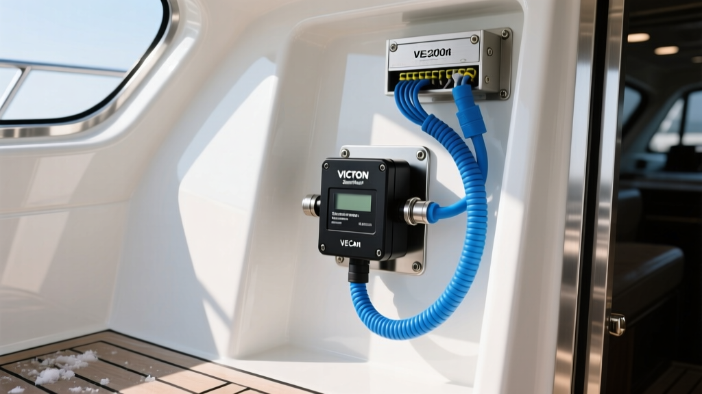
For vessels running lithium house banks, integrating a battery monitor is vital. The Victron SmartShunt 500A features a VE.Can port that allows it to broadcast State of Charge (SOC), voltage, and time-to-go data directly to compatible chartplotters like the Raymarine Axiom or Garmin GPSMAP series. According to the Victron Energy VE.Can Setup Guide, you will need the Victron RJ45 to NMEA 2000 adapter cable (Part # ASS030532000). Plug the RJ45 end into the SmartShunt's VE.Can port, and the Micro-C end into the backbone. Set the VE.Can instance number to '0' in the VictronConnect app to ensure the chartplotter prioritizes this data stream.
Troubleshooting Common Network Errors
Even with meticulous planning, marine vibrations and saltwater corrosion can introduce faults. Here is a diagnostic matrix for the most common NMEA 2000 error codes displayed on modern MFDs (Multi-Function Displays):
- Network Terminator Missing: The MFD cannot detect the 120-ohm resistance at the ends of the backbone. Check that both end caps are securely screwed on and that you haven't accidentally installed three terminators on a branched network.
- Network Power Fault (Low Voltage): Voltage at the MFD has dropped below 9V. Check your inline fuse, verify the power T-connector is centered on the backbone, and ensure the battery voltage is above 12.4V.
- Data Source Conflict: Two devices are broadcasting the same PGN (Parameter Group Number), such as two GPS antennas sending heading data. Go into your MFD's "Device List" and manually disable the secondary GPS antenna's "Transmit PGN" setting.
- Node Overloaded: You have exceeded the maximum current draw of a single T-connector (usually 3A). If you are powering high-draw gadgets like an active sonar module, use an inline network power extender to inject additional current into that specific segment.
Final System Testing and Maintenance
Once all boating gadgets are physically connected and the network is powered, perform a "Network Scan" from your primary chartplotter. Verify that every device appears in the list with a green status indicator. Take the vessel out on the water and run the engine up to cruising RPMs; the alternator's voltage spike and the hull's vibration will quickly reveal any loose locking collars or poorly crimped power connections.
For annual maintenance, inspect every T-connector for signs of green copper oxide corrosion. Even marine-grade brass contacts can degrade. Unscrew the collars, inspect the O-rings for flattening or cracking, and apply a thin layer of dielectric grease or a specialized marine contact enhancer like Caig DeoxIT before resealing the connections. By treating your NMEA 2000 backbone with the same respect as your vessel's primary DC electrical system, your boating gadgets will deliver seamless, integrated performance for years to come.
Written by
Priya SharmaPriya Sharma holds a Ph.D. in Acoustical Engineering from the University of Southampton and a B.Tech in Electronics from IIT Delhi. She has spent 9 years as a consumer electronics journalist, with deep specialization in audio equipment, camera systems, and assistive technology. Priya is an active member of the Audio Engineering Society (AES) and has co-authored papers on spatial audio perception published in the Journal of the Acoustical Society of America. Her reviews of headphones, portable DACs, and studio monitors include objective measurements using Audio Precision analyzers alongside subjective listening tests. She also serves on the advisory board of the Global Accessibility Reporting Initiative (GARI), evaluating mobile devices for users with visual and hearing impairments.